
At Sierra Pacific Engineering & Products, we create custom parts for our customers through our parts engineering program. As part of this, we model parts in Solidworks to get the details worked out before they are ready for prototyping and production. While we are happy to do the full design process, or work collaboratively with our customers, we know that some of our customers want to model their parts themselves.
Want to learn how to use Solidworks like a pro? Step through the process of creating threads with the engineers at SPEP. Learn basic and more advanced techniques such as how to make threads in Solidworks using three different methods.
1. Making Cosmetic Threads with Solidworks
Depending on your needs, cosmetic threads may be sufficient. These are not modeled to your exact engineering requirements but instead provide the appearance of threads as a ‘skin’ applied to other features in your model. However, if you are designing a product and know that you will use a stock fastener, you may not need to have an exact replica in the Solidworks mockup. This is especially true for preliminary designs.
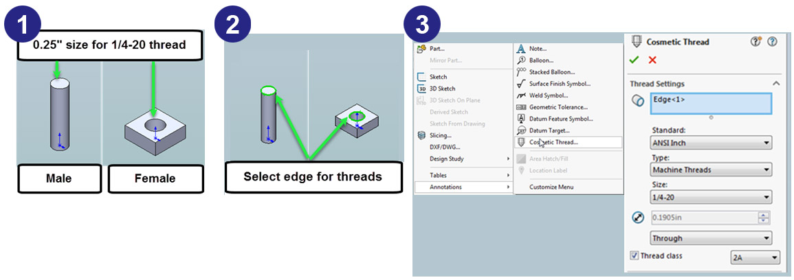
To create cosmetic threads:
- Start by creating a cylindrical extrusion (for the male thread) or a cylindrical hole (for the female thread).
- Then, select the edge where the thread will start.
- Finally, click “Insert” then “Annotations” then “Cosmetic Thread.” This will give you an opportunity to define the size, end conditions and thread class.
That’s it! You’ve learned how to make threads in Solidworks the easy way!
2. Using the Built-In Solidworks Thread Feature
If you want something a little more exact, you could easily model a thread using the built-in thread feature. This is a good way to achieve reasonably realistic modeling with minimal work. You may want to use this method if you just need a thread that works or want to use it as a jumping-off point for custom modeling.
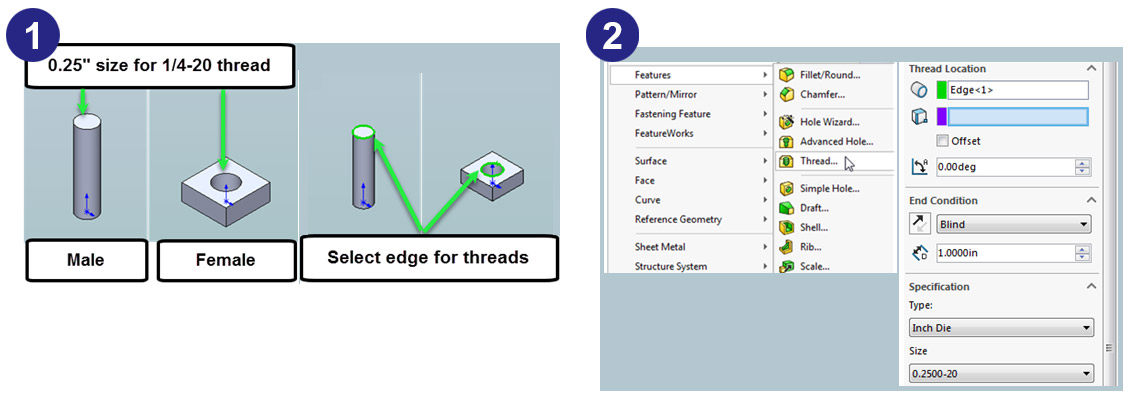
- Start by creating a cylindrical extrusion or cylindrical hole, much like the initial steps to of making a cosmetic thread. The feature size should be the same as the nominal thread diameter. From there, select the starting edge.
- Then, click “Insert” then “Feature” and “Thread.” This will automatically create a thread. You can define the end condition, size and various thread specifications. Simply play around with these settings until you’ve got it the way you want it.
With that, you’ve modeled threads in Solidworks. This feature is almost as fast and easy as creating a cosmetic thread. It offers a great balance between speed and accuracy.
3. Custom Modeling Threads
Finally, you may find yourself in a situation in which you want a little more control. This may be the case if you are expecting to create a custom fastener. The thread needs to be highly accurate if you intend to create a mold or 3D print the part.
Additionally, you may want to custom model a thread if the built-in feature is not sufficient. This may be the case with an irregular thread or a special-use thread such as for wood or plumbing. Whatever your reason for modeling the thread manually, these are the typical steps:
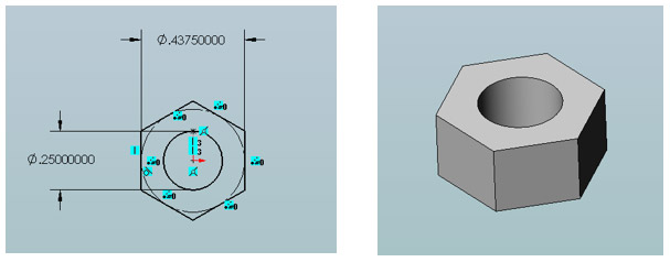
- Create the 3D Shape: Begin by modeling the primary shape up to the point where you would add the thread. You will likely want to model both the part with the male thread and the part with the female thread.

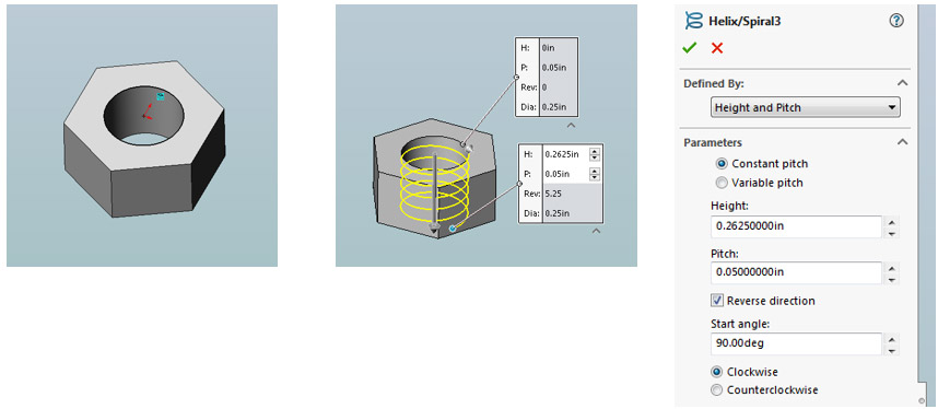
- Create Helical Spiral: Select the edge that the thread will start from. Draft a circle that matches the thread major diameter. Then, click “Insert” then “Curve” and “Helix and Spiral.” Define the helix by height for the thread length and pitch for the thread pitch. Additionally, make sure it twists the right way. A right-hand thread is typically clockwise, and a left-hand thread is counterclockwise.

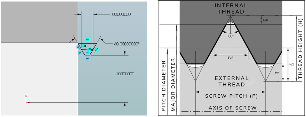
- Create the Thread Teeth Profile: Define the thread teeth profile on the plane normal to the thread path. This should be based on the screw pitch, minor diameter, thread angle and other required dimensions. You can refer to specs such as ASME/ANSI 81 or ISO 965-1 to determine the thread profile for your fastener.

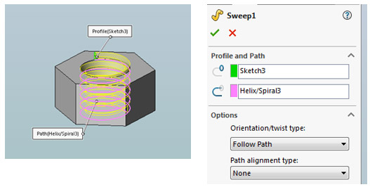
- Generate the Custom Thread: Create a sweep or swept cut to make your custom thread. At this point, you have modeled it and are almost finished.

- Clean-Up: The final step is to clean up some of your work. This should include cutting or extruding any excess surfaces. You should also chamfer near side edges.

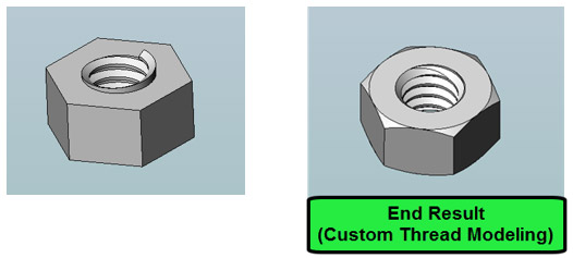
Now you know how to make threads in Solidworks from scratch. This gives you the option to completely define your thread characteristics with maximum control compared to the other two methods.
Keep in mind, however, that the more complex the thread, the larger the file size and the longer the rebuilding time. Method one will create the most condensed files followed by method two and finally method three. So, while custom modeling can give you a lot of authorial control, consider only using it when necessary.
Get Expert Help from SPEP
The SPEP team is happy to help with all your Solidworks needs. We can design any part you may need. However, if you want to delve in a little yourself, the above how-to and our other guides will help you master the program. Our goal is to ensure that you get the right part for the right price at the right time. Contact us to learn more.
Looking for more Solidworks How To’s? Learn how to make springs and more with SPEP.
Editor’s Picks

Sierra Pacific Engineering College Scholarship Program
Feb 7, 2022

What is Supply Chain Management, and Why Is It Important?
Jan 13, 2022
How To Make Threads in Solidworks: Become a Solidworks Expert
Nov 10, 2020
Recent Posts

Chain Retainers
Why High-Quality Chain Retainers Matter: Strength, Safety, and Reliability In industrial settings, even small parts can significantly impact safety and performance. Chain retainers are a great example; they keep safety chains in place to help prevent costly and...
The Ultimate Access Upgrade
Designing access panels, enclosures, and HVAC systems is all about balance: making things flexible for users while keeping your design simple, reliable, and affordable. Too often, traditional hardware forces you to compromise — settling for a hinge that only opens one...

How to Install a Magnetic Push Latch
Latches are essential components of access hardware. They are designed to temporarily join two or more objects or surfaces while allowing for easy separation. This action provides security for doors, gates, cabinets, or any other enclosure to protect valuable items. ...