
Solidworks is at the heart of Sierra Pacific Products and Engineering’s custom part design process. Although we are happy to handle all the modeling ourselves, some of our clients are eager to learn about Solidworks so they can better communicate their ideas and requirements.
If you are interested in learning how to use Solidworks like a pro, we have provided step-by-step instructions on how to make a spring in Solidworks based on the expert knowledge of SPEP engineers’. Learn how to change materials, create threads and much more.
How To Use Solidworks – The Basics (At The Part Level)
Before learning to make a spring, it is helpful to understand a few basics of Solidworks. After mastering these fundamentals, you will be ready to learn more. Whether you want to learn how to make a gear in Solidworks or a complex multi-component device, starting at the beginning is important.
How To Change Units in Solidworks
There are a few unit options in the program. The most significant distinction is between choosing imperial or metric units. These are the options:
- Inch, pound, second
- Millimeter, gram, second
- Centimeter, gram, second
- Meter, kilogram, second
You can switch between them in two ways. To change the unit system for a document, click “Tools” then “Options” then “Document Properties” and select “Units”. You can also change the unit system at the document template level and implement consistently on all new documents.
How To Change Material in Solidworks
Managing your materials in Solidworks is essential for accurately calculating weights for each component or device you are creating in the program. The process for assigning a material to a part is very simple. Just right-click “Material” in the feature manager design tree then “Select Material”. Lastly, select the material you want to use and click “Apply” followed by “Close”.
How To Scale in Solidworks
Scaling is another important element of using Solidworks. In the part document, simply click “Scale” then set the options in the pop-up window. Finally, click the checkmark to finish scaling. Note that scaling is not common at the part level. It’s commonly addressed in the drawing level
Steps for Making a Spring
Now that you are familiar with some of the basics of Solidworks, you are ready to make a spring. The following steps can be used to make an open spring (with rounded ends) or a ground spring (with flat ends).
-
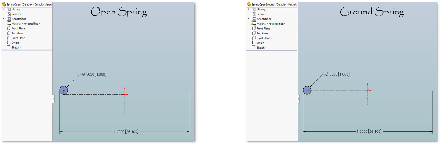
- Step 1 – Make a Wire Sketch
Start by creating a wire sketch on the front plane. Make sketch lines to determine the wire circle location. Set the diameter of the spring per your requirements. Make sure you are setting the center, outside or inside diameter based on your preference. For the open spring, the center line for the spring diameter should connect with the bottom tangent of the wire circle. For the ground spring, it is to the center of the circle.

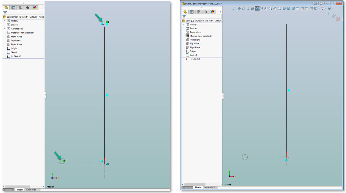
- Step 2 – Make a Length Sketch
Create a new sketch on the front plane with a construction line. This line should not be fully defined to help achieve the desired dynamic spring. For an open spring, at the top of the construction line, there should be a perpendicular line that is equal to the inside diameter of the wire circle.

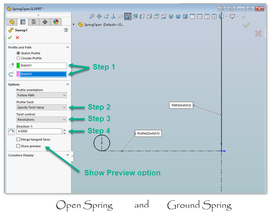
- Step 3 – Implement a Sweep
- Select the sweep feature. Then, follow these steps for both types of springs:
- Select “Profile” sketch and “Path” sketch.
- Select “Profile Twist Value” in the “Profile Twist” drop down menu.
- Select “Revolutions” from the “Twist Control” drop down menu.
- Select the preferred rotation direction and number of revolutions per your requirements.

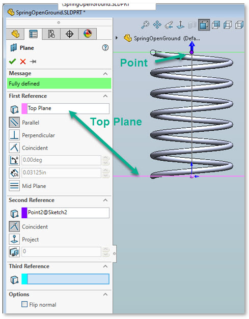
- Step 4 – Create a Parallel Plane
Now that you have learned how to make threads in Solidworks for your spring, you may want to add flat ends for a ground spring. For an open spring, skip to step seven. Select the second sketch. Create a plane perpendicular to the centerline of the spring. This should be parallel with the top plane. These planes will mark where your ground spring flat ends are cut off.

- Step 5 – Add Top Flat End
Select the plane at the top of the spring. Then, insert a cut to the material with the SurfaceCut feature. Make sure the direct the cut away from the spring.

- Step 6 – Add Bottom Flat End
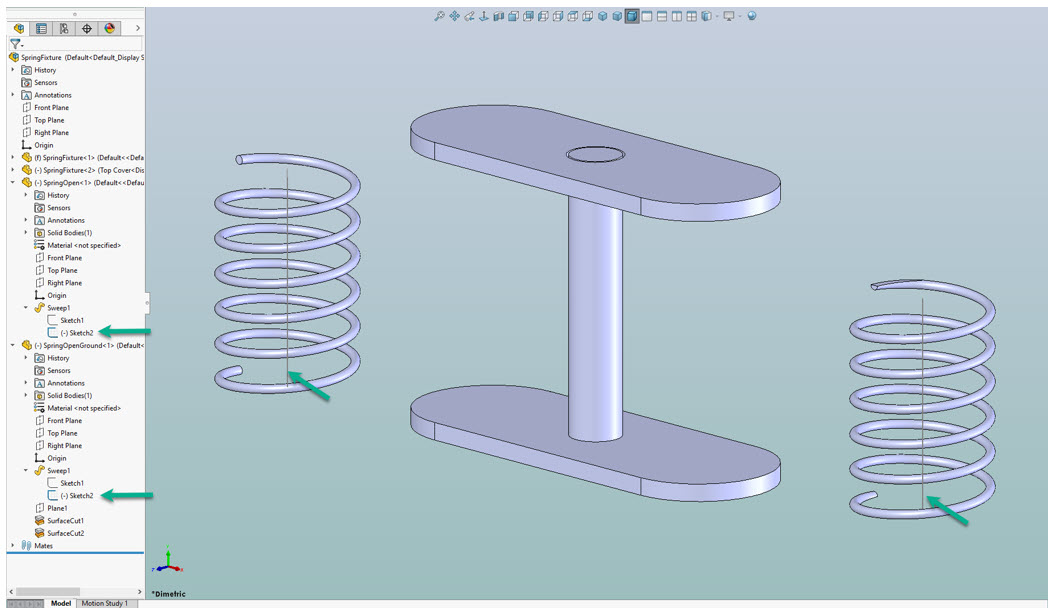
Repeat the same for the bottom flat end. At this point, your ground spring is ready to be inserted into an assembly design. - Step 7 – Insert Into Assembly
Depending on what you intend to do with your spring design, you can use it in an assembly or just send it to the SPEP engineers. We are happy to work with your part design. Alternatively, we can add other features as you may need.

- Step 1 – Make a Wire Sketch

How To Render in Solidworks
If you want to show off your design, you may want to create a rendering of the 3D model. To do this, click “Tool” then “Add-ins”. Add PhotoView 360. Start a previous in the graphics area and make whatever changes you need such as scene and decals. Make sure to position and edit the lighting to achieve your desired look. You can also play around with the PhotoView options if you like. Finally, click “PhotoView” then “Final Render” to export a rendering of the part.
Get Expert Help From SPEP
Whether you want to make your own part design in Solidworks or let the SPEP team handle the design process from the beginning, we are here to help. Our goal is to ensure that you get the right part for the right price at the right time. Contact us to learn more.
Editor’s Picks

Sierra Pacific Engineering College Scholarship Program
Feb 7, 2022

What is Supply Chain Management, and Why Is It Important?
Jan 13, 2022

How To Make Threads in Solidworks: Become a Solidworks Expert
Nov 10, 2020
Recent Posts

Chain Retainers
Why High-Quality Chain Retainers Matter: Strength, Safety, and Reliability In industrial settings, even small parts can significantly impact safety and performance. Chain retainers are a great example; they keep safety chains in place to help prevent costly and...
The Ultimate Access Upgrade
Designing access panels, enclosures, and HVAC systems is all about balance: making things flexible for users while keeping your design simple, reliable, and affordable. Too often, traditional hardware forces you to compromise — settling for a hinge that only opens one...

How to Install a Magnetic Push Latch
Latches are essential components of access hardware. They are designed to temporarily join two or more objects or surfaces while allowing for easy separation. This action provides security for doors, gates, cabinets, or any other enclosure to protect valuable items. ...