Today’s manufacturers face a lot of challenges and solutions their predecessors could only dream about. Between the wide range of new materials being developed, the increasing complexity of goods manufactured in almost every industry, and the increased sophistication of designers’ tools, they are expected to produce at a level of sophistication that breaks new territory every year.
On top of that, the increase in technological development toward specialization and precision is not linear, it’s accelerating. That means each passing year requires you to do more, faster, with even more new tools and materials. That can be a lot to manage, and you need to be able to simplify your processes wherever possible to ensure a consistency to your product quality and to keep everyone at every stage of design and delivery on the same page about the goals and materials being used. That’s where 3D modeling can really help.
Communicate Clearly with Downstream Operators
The biggest obstacle to successfully manufacturing to a precise and complex set of specifications is clear communication. When the people building components for your product can’t see how everything comes together for themselves, they often misunderstand important parts of their own process, leading to assumptions that can hinder the project. One of the key advantages you gain when using 3D modeling in your manufacturing design process is the ability to then show that working system of components to the engineers, fabricators, and other skilled players in your supply chain and assembly line. It makes project management easier when you can be sure everyone can see and interact with the end result.
It’s not just the visual depiction of a working model that adds information, either. 3D CAD/CAM systems allow for in-line annotation, which makes it even easier to make sure you communicate exactly what you need when sending information out to suppliers who will build your components.
- Part dimensions and geometry
- In-line tolerance annotations
- Material specification annotations
- Use custom measurements or indicate standard component sizes for assembly steps
All of this information is not only present, but in 3D modeling environments, it’s presented in-line as part of the design layout. Using Geometric Distancing & Tolerancing, the universal language for depicting these specifications, increases information density while simplifying explanations by resolving all your requirements into a common language you can count on downstream users understanding when you send your plans out.
Improved QA at Every Step of the Process
Presenting all of this data in-line represents a huge simplification over the way the same knowledge was transmitted in 2D engineering drawings. 2D models require the downstream user to assemble a total idea of the product themselves, since each depiction can show only one side, and along with it one set of tolerances. Users then have to build the molds, dies, and other components that manufacture your part using an incomplete view at any given time. This results in more revisions to reconcile different project demands as the design process unfolds, and it also increases the complexity of the work done by QA teams to monitor the manufacturing process after you go into production.
This simplification of the plans and placement of the specifications allows for easier cross-referencing, but that’s hardly all. 3D modeling also allows you to gain vantage points not provided by 2D models, so your downstream build team can see how the dimensions look from every angle. The result is a simpler interpretation of specs, so even if the precision of the work remains the same, the process of ensuring quality gets easier with 3D modeling than it could without.
Efficient Updates During Design Revisions
Using 2D engineering drawings means having to send out updates that take time to disseminate and interpret. The resulting lag can slow down the production of revised prototypes or components to make them. When you use 3D modeling and a cloud-based system for communicating them to other locations and teams, your changes update instantly to everyone in the production stream. That means less time to get each piece of the puzzle revised, better quality control as changes are made, and as a result, you see the way revisions change the product more quickly. That increased efficiency allows you to tighten the design process and move from concept to production with fewer delays and hiccups. In a manufacturing environment where your competition is already trying to out-design your next generation of products before you’ve even released the current one, you need every advantage you can get.
Update Your Design Software Today
There are many industries that embraced 3D modeling over the last couple decades, but the adoption has been incredibly lopsided. While you will find many companies and even industries that take it for granted that plans will be in 3D, there are many more where that upgrade will still stand out as a mark of innovation. Even where 3D models are widespread, the sophistication of the software and its flexibility with regard to data sharing and security make a huge difference, so the most competitive actors in the field are the ones who stay up to date on their design tools.
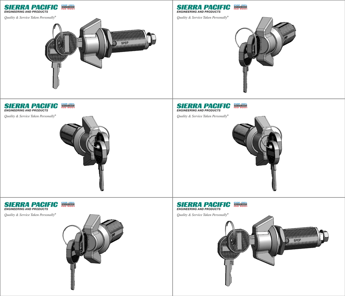
Sierra Pacific Engineering & Products makes their parts available in 3D. Simply follow the instructions associated with the CAD 2D/3D icon for part you need. Once you have the part electronically, you can simply drop it into your design.
Editor’s Picks

Sierra Pacific Engineering College Scholarship Program
Feb 7, 2022

What is Supply Chain Management, and Why Is It Important?
Jan 13, 2022
How To Make Threads in Solidworks: Become a Solidworks Expert
Nov 10, 2020
